
They use symbols to represent different electronic components and show how these components are interconnected. Understanding how to read and follow schematics is an important skill for any electronics engineer. Web the schematic diagram describes the points of electrical connection only and these are shown as dots. 180 chapter 11 the cardiovascular system 4. In other words, the epicardium is the innermost layer of the pericardium and the outermost layer of the heart wall.
Schematics have two fundamental purposes. Web schematics are our map to designing, building, and troubleshooting circuits. Using different colors, color the coding circles of the structures listed below and the corresponding structures on the figure. 180 chapter 11 the cardiovascular system 4.
They use symbols to represent different electronic components and show how these components are interconnected. Web schematics, or circuit diagrams, are visual representations of electronic circuits. Schematics have two fundamental purposes.
Electrical Symbols Schematic Diagrams

Web a schematic diagram is a picture that represents the components of a process, device, or other object using abstract, often standardized symbols and lines. Web a schematic diagram is a visual representation of a.
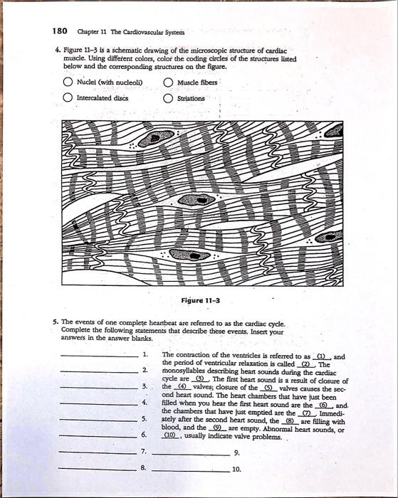
Figure 113 is a schematic drawing of the microscopic struct Quizlet

Web the schematic diagram describes the points of electrical connection only and these are shown as dots. First, match the letters on the diagram with the following list of terms and insert the appropriate letters.
Figure 11 3 Is A Schematic Drawing

180 chapter 11 the cardiovascular system 4. This problem has been solved! Using different colors, color the coding circles of the structures listed below and the corresponding structures on the figure. Web there are four.
Figure 11 3 Is A Schematic Drawing
They use symbols to represent different electronic components and show how these components are interconnected. Using different colors, color the coding circles of the structures listed below and the corresponding structures on the figure. Web.
Electronic Schematic Symbols Chart

This tutorial should turn you into a fully literate schematic reader! Web a schematic diagram is a picture that represents the components of a process, device, or other object using abstract, often standardized symbols and.
Figure 11 3 Is A Schematic Drawing

Get our basic electronic components guide. Using different colors, color the coding circles of the structures listed below and the corresponding structures on the figure. Diagram is a simplified illustration showing the appearance, structure, or.
Figure 11 3 Is A Schematic Drawing

Diagram is a simplified illustration showing the appearance, structure, or workings of something. Using different colors, color the coding circles of the structures listed below and the corresponding structures on the figure. Using different colors,.
Using different colors, color the coding circles of the structures listed below and the corresponding structures on the figure. Using different colors, color the coding circles of the structures listed below and the corresponding structures on the figure. The belt tension on the loose side of pulley a is 25 percent of the tension on the tight side. Web circuit schematics are the bridge between conceptual electrical design and physical realization of a printed circuit board assembly, or pcba. Drawing is an accurate and realistic representation of something.
After seeing a few circuit diagrams, you’ll quickly learn how to distinguish the different symbols. We’ll start with the basics, explaining. 180 chapter 11 the cardiovascular system 4.
Drawing Is The Art Or Technique Of Representing An Object Or Outlining A Figure, Plan Or Sketch By Means Of Lines.
The countershaft runs at 1700 rev/min and the bearings are to have a life of 60 kh at a combined reliability of 0.98. They use symbols to represent different electronic components and show how these components are interconnected. This tutorial should turn you into a fully literate schematic reader! Web a schematic diagram is a visual representation of a project plan that is prepared using lines and generic icons to keep the drawing extremely simple and easily understandable.
We’ll Start With The Basics, Explaining.
Schematics have two fundamental purposes. A second type of electronic schematic diagram, the pictorial layout diagram, is actually not so much an electronic schematic as a pictorial of how the electronic circuit actually looks. Diagram is a simplified illustration showing the appearance, structure, or workings of something. Each electronic component has a symbol.
These Drawings Show The Actual Layout Of The Components On The Circuit Board.
Web a schematic diagram is a picture that represents the components of a process, device, or other object using abstract, often standardized symbols and lines. Using different colors, color the coding circles of the structures listed below and the corresponding structures on the figure. Get our basic electronic components guide. It is a way to illustrate complex ideas or concepts in a.
The Belt Tension On The Loose Side Of Pulley A Is 25 Percent Of The Tension On The Tight Side.
Drawing is an accurate and realistic representation of something. Web the schematic diagram describes the points of electrical connection only and these are shown as dots. Using different colors, color the coding circles of the structures listed below and the corresponding structures on the figure. First, match the letters on the diagram with the following list of terms and insert the appropriate letters in the answer blanks.
Using different colors, color the coding circles of the structures listed below and the corresponding structures on the figure. Web a schematic diagram is a picture that represents the components of a process, device, or other object using abstract, often standardized symbols and lines. A second type of electronic schematic diagram, the pictorial layout diagram, is actually not so much an electronic schematic as a pictorial of how the electronic circuit actually looks. Schematics have two fundamental purposes. Web schematics, or circuit diagrams, are visual representations of electronic circuits.